


Icon16 / Logicom


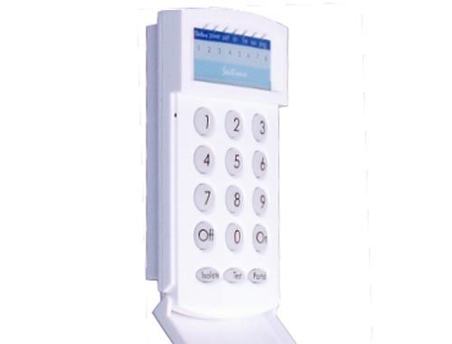
Arm Disarm Bypass
Arming Areas with a User Code:
Notes:
- User codes may be allocated to control any combination of Areas and can only Arm and Disarm these pre-programmed Areas.
- An Area will not Arm unless all section lights in the Area are out or the section is Isolated.
- If a Section is already Isolated before Arming, it will remain Isolated until the Area is Disarmed.
- Power light should be ON and not flashing. (Unless Partial or Isolate keys have been pressed.)
- Any section may be programmed to have Exit Time. The Exit Timer starts as soon as the Area is Armed and the Area light starts flashing. The beeper beeps while the Exit timer is running.
- Exit only via programmed Exit/Entry sections in the area that is being Armed.
- If the Exit / Entry sections are not sealed when the exit timer expires then the siren will give a 2 second warning and the entry timer is started. If the area is not turned OFF before the entry time expires a full siren / strobe and alarm transmission to the Central Station will occur.
- When a user code is entered, all the Areas that the code is permitted to control are selected for arming. To limit which areas are selected, the Part or Partial key may be pressed. Specific Areas may then be selected for Arming.
- When Partial Area arming is selected, the area indicators will be ON if the Area is Armed, OFF if the Area is not Armed or flashing if it is selected for partial Area Arming.
Key Sequence Operation:
[1] [2] [3] [4] [On]
Example shows a User Code 1 2 3 4 being used to arm all it’s Areas.
[1] [2] [3] [4] [partial] [4] [5] [On]
Example shows a User Code 1 2 3 4 selecting partial to arm areas 4 and 5.
Disarming Areas with a User Code:
Notes:
- User codes can be allocated to control any combination of Areas and can only Arm and Disarm these pre-programmed Areas.
- This key sequence also acknowledges or silences the siren / strobe if an alarm is activated.
- When a user code is entered, all the areas that the code is permitted to control are selected for disarming. To limit which areas are selected, the partial key may be pressed then specific Areas may be selected for Disarming.
- All non 24 hour sections that are isolated will be De-Isolated when an area is disarmed.
Key Sequence Operation:
[1] [2] [3] [4] [Off]
Example shows a User Code 1 2 3 4 being used to dis-arm all it’s Areas . (Isolated Sections will Slow Flash)
[1] [2] [3] [4] [partial] [4] [5] [Off]
Example shows a User Code 1 2 3 4 selecting partial mode to dis-arm areas 4 and 5.
Isolating a Section:
Notes:
- When a valid user code has been entered and the isolate key has been pressed, all isolated sections will be Slow Flashing. Any section may be Selected or De – Selected and only sections that are Slow Flashing will be isolated when the Area is On.
- An Area may be armed or disarmed with sections Isolated. Only sections that are allocated to the Area being armed may be isolated. Any other section that has been selected for isolation will be ignored.
- If disarming an area then only 24 hour sections may be isolated.
- When entering section numbers a two digit number must be used. (On some panels that have only 8 possible sections this may be reduced to single digit entry. i.e. the leading zero is ignored)
- Only valid section numbers may be entered.
- Non 24 hour sections are automatically de-isolated when the Area is turned OFF.
Key Sequence Operation:
[1] [2] [3] [4] [isolate] [0] [4] [0] [7] [On]
Example shows a User Code 1 2 3 4 being used to enter Isolation mode. Sections 4 and 7 are being Isolated in the Area the User Code is allocated. When desired sections are isolated turn the Area to ON mode.
Code Changes
Changing User Codes:Functions 01-90
Notes:
- Default User Code 01 is.. 1111 with Areas 1, 2, 3, 4, 5, 6, 7, 8.
- User codes are 4 digits long and can be allocated to control any combination of areas.
- User codes are used to change the status of panel, isolate sections or acknowledge alarms.
- User codes cannot be the same or within one count of another User code or be the first 4 digits of the 6 digit Master Code or Technician Code.
- To change User codes all areas must be in the OFF mode.
- Area 7 is not a physical area but is used to limit access to panel test functions and print requests. (Enable area 7 for the user code that will be used for test functions and print requests.)
- Area 8 is not a physical area but is used to inhibit a user’s ability to isolate a section.
- To delete a user code enter the [isolate] key as the new code.
Key Sequence Operation: Change User Code
[2] [1] [8] [5] [7] [2] [On]
Example shows Master code 218572 used to enter program mode.
[0] [1]
Select a User code (01-90). Example shows 01.
[1] [2] [3] [4] [On]
Enter and Store new user code 1 2 3 4.
[0] [1] [partial]
Select User code 01 area allocation mode.
[0] [4] [0] [5] [On]
Select area 4 and 5 then store. Finish selection and exit area allocation mode.
[Off]
Exit program mode.
Key Sequence Operation: Deleting User Code
[2] [1] [8] [5] [7] [2] [On]
Example shows Master code 218572 used to enter program mode.
[0] [2] [isolate] [On]
Select and delete user 02.
[Off]
Exit program mode.
Keypad Functions
Keypad Panic:
The keypad panic may be initiated by holding both the [ON] and the [OFF] keys depressed together for a period of 3 seconds. If the alarm system is monitored a duress report will be sent to the monitoring station and, if enabled by the installer, the sirens will sound.
Duress Code:
Keypad duress must be enabled by the installer at installation and is initiated by incrementing the last digit of a valid user code by 1. For example, if the users code was 1234, then a duress signal would be sent to the monitoring station if the user entered 1235 as their code. In all other respects the panel would react as if the normal code had been entered.
For user codes ending in 9 then a 0 would be entered eg. normal code is 1949, duress code would be 1940.
Memory & Trouble
Keypad – Indicators:
| Section Lights | There are up to 48 section lights on the keypad. |
|---|---|
| When the Area is in the OFF mode, the sections for that area are not armed (except for 24 hour sections) and the Section Lights indicate the condition of the sensor. | |
| When the Section Light is ON, the sensor is activated e.g. door contact detecting door open or motion detector sensing movement. | |
| When the Section Light is OFF the sensor is not activated. | |
| When the Area is in the ON mode, the sections for that area are armed. If the section light is Flashing the sensor is activated and triggers the siren and strobe light (unless programmed to be silent). This alarm is transmitted to the Central Station. | |
| When the Area has been Armed, an exit timer starts and holds the sections that have been programmed for Exit delay disarmed. This allows the user to exit the premises without activating the alarm. | |
| When the Area is Armed, and the Exit timer has finished, Entry into the premises can be made via a section that has Entry delay. This will start the Entry delay. If the Area is disarmed before the Entry Delay Timer expires, there will be no alarm. | |
| Program Light | When fitted, this Light will be ON when a Master code is entered and the user codes are being viewed or changed. |
| Program Light is also On when a user code is in Isolate or Test modes. | |
| Power Light | This light is normally ON. This indicates that the Plug Pack power and backup battery are normal. |
| When the mains has failed the power light will single flash. | |
| When the battery is low in voltage, the power light will double flash. | |
| Fast flashing while in Program mode. | |
| Power Light | ON when the Area is armed. |
| Single flash when the Area is armed and the Exit timer is running. | |
| Double flash when a section in Alarm for that Area or the Entry timer is running. | |
| OFF indicates Area is not Armed. |
Reset Fire Alarms
[1] [2] [3] [4] [Test]
Example shows a User Code 1 2 3 4 being used to enter test mode.
[6]
Reset Smoke Detectors (if fitted) – removes power from the smoke detectors for 5 seconds.
[Off]
Exit test mode.
Setting Date & Time
Changing Time and Date: Functions 97 and 98
Notes:
1. All areas must be in Off mode.
2. The Time setting is changed with Function 97 and is 4 digits long. The format is HH MM where: HH is hours (00 – 23), MM is minutes (00 – 59).
3. The Date setting is changed with Function 98 and is 6 digits long. The format of DDMMYY where: DD is the day (01-31), MM is the month (01-12), YY is the year (00 – 99).
Key Sequence Operation:
[2] [1] [8] [5] [7] [2] [On]
Example shows Master code 218572 used to enter program mode.
[9] [7]
Select Function 97 Time set.
[1] [9] [3] [0] [On]
Enter new time. Example shows 7:30 pm
[9] [8]
Select Function 98 Date set.
[0] [4] [1] [0] [9] [7] [On]
Enter new date. Example shows 4 October 1997.
[Off]
Exit program mode with the OFF key.
Test Mode Functions
Notes:
- Test your system regularly and this will keep you familiar with the system and confident in the systems operation.
- Maximum testing time is 10 minutes.
- All Areas must be in the OFF mode before entering test mode.
- Test modes described below.
| Test 1 | Walk test– Beeper and section light operates. This test enables the user to walk around and activate sensors and check correct operation of sensors. |
|---|---|
| Test 2 | Siren test– Siren sounds for 3 seconds. |
| Test 3 | Strobe test – Strobe operates until next key press. |
| Test 4 | Test all lights and beeper operates until the next key is pressed – used to check operation of lights and beeper. |
| Test 5 | Recall Last Alarm– last alarm flashes until next key press. |
| Test 71 | Print a report– of the last 150 events in the Event log. |
| Test 70 | Print a report of the all the events in the Event log (1000). Test mode is exited. Abort print report by pressing any key. |
| Test 9 | (Dialler Only) Sends a Test Message to the Central station. Test mode is exited. |
Key Sequence Operation:
[1] [2] [3] [4] [Test]
Example shows a User Code 1 2 3 4 being used to enter test mode.
[1]
Test 1 started – walk test
[2]
Test 2 started – siren test
[Off]
Exit test mode.
View Cheatsheet
ARMING THE SYSTEM
Ensure all sections lights are off
[CODE] + [ON]
DISARMING THE SYSTEM
[CODE] + [OFF]
ARMING/DISARMING SELECTED AREAS
[CODE] + [PATRIAL] + [4] + [5] + [ON]
example shows user code selecting patrial to arm areas 4 & 5
[CODE] + [PATRIAL] + [4] + [5] + [OFF]
example shows user code selecting patrial to disarm areas 4 & 5
BYPASSING / ISOLATE
[CODE] + [ISOLATE] + [ZONE# ] (e.g. [04] for zone 4) + [ON]
all isolated zones will be slowly flashing
RESETTING SMOKE ALARMS
[CODE] + [TEST] + [6] + [OFF]